|
|
|
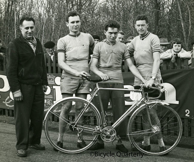
Correspondence still with the bike tells that it was ordered in the summer or fall of 1974 and delivered to its original owner, my friend Richard Payne, in Tunisia on or about August 7, 1976 ("Dick" also lived in Santa Cruz, California, where I knew him). According to Jan's book, René Herse was in poor health during these years and died on May 12, 1976. So, it's likely that this bicycle was one of the last built during Herse's life. From its details, Jan believes it was built by Jean Desbois, who Jan said, Herse hired as an apprentice when Jean was 17 years old and just out of high school.
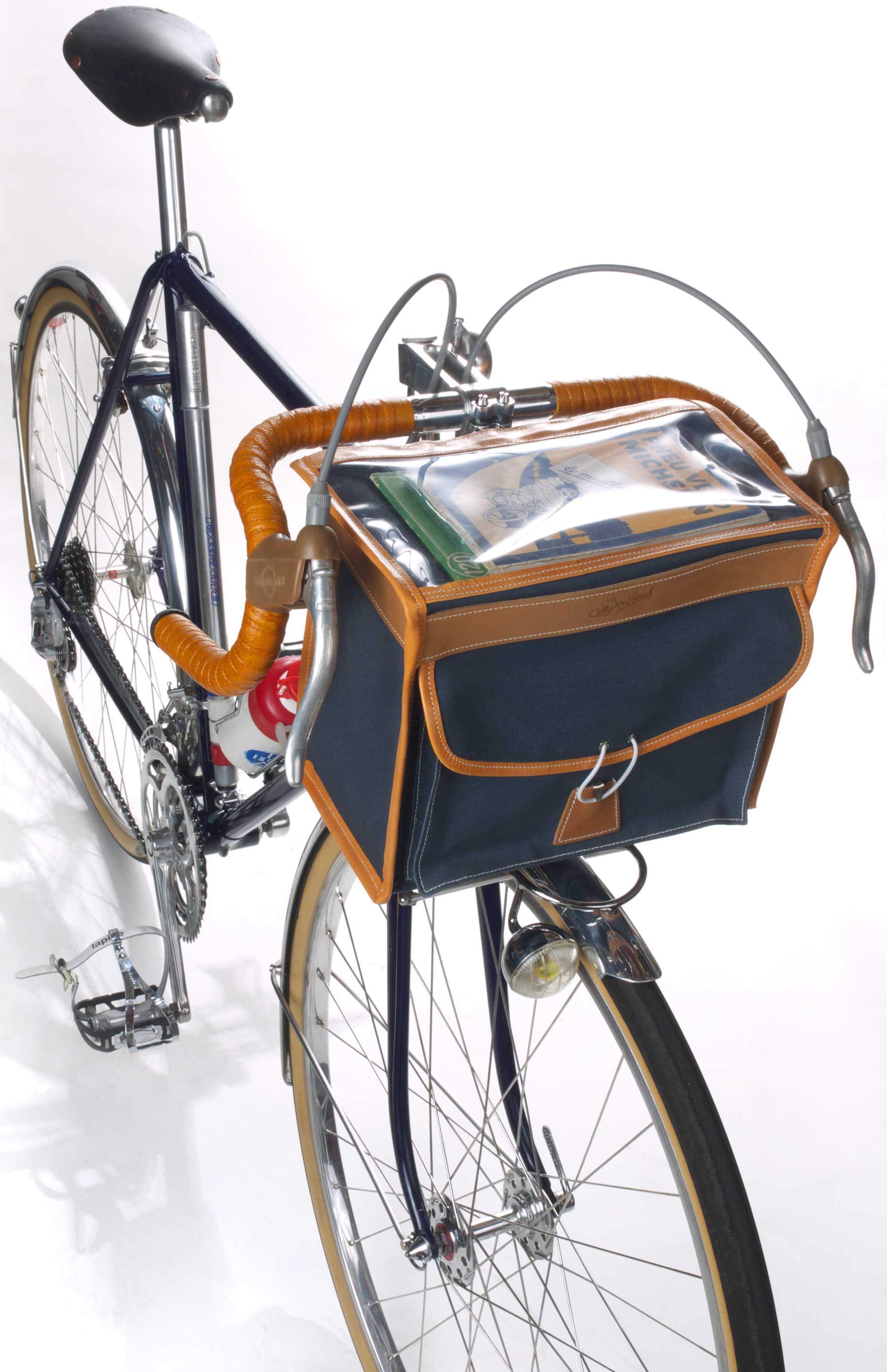
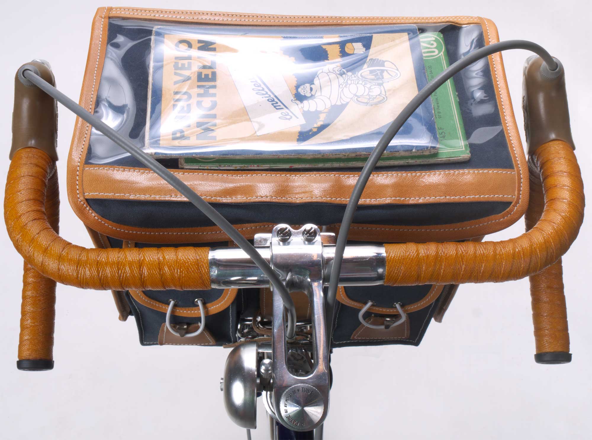
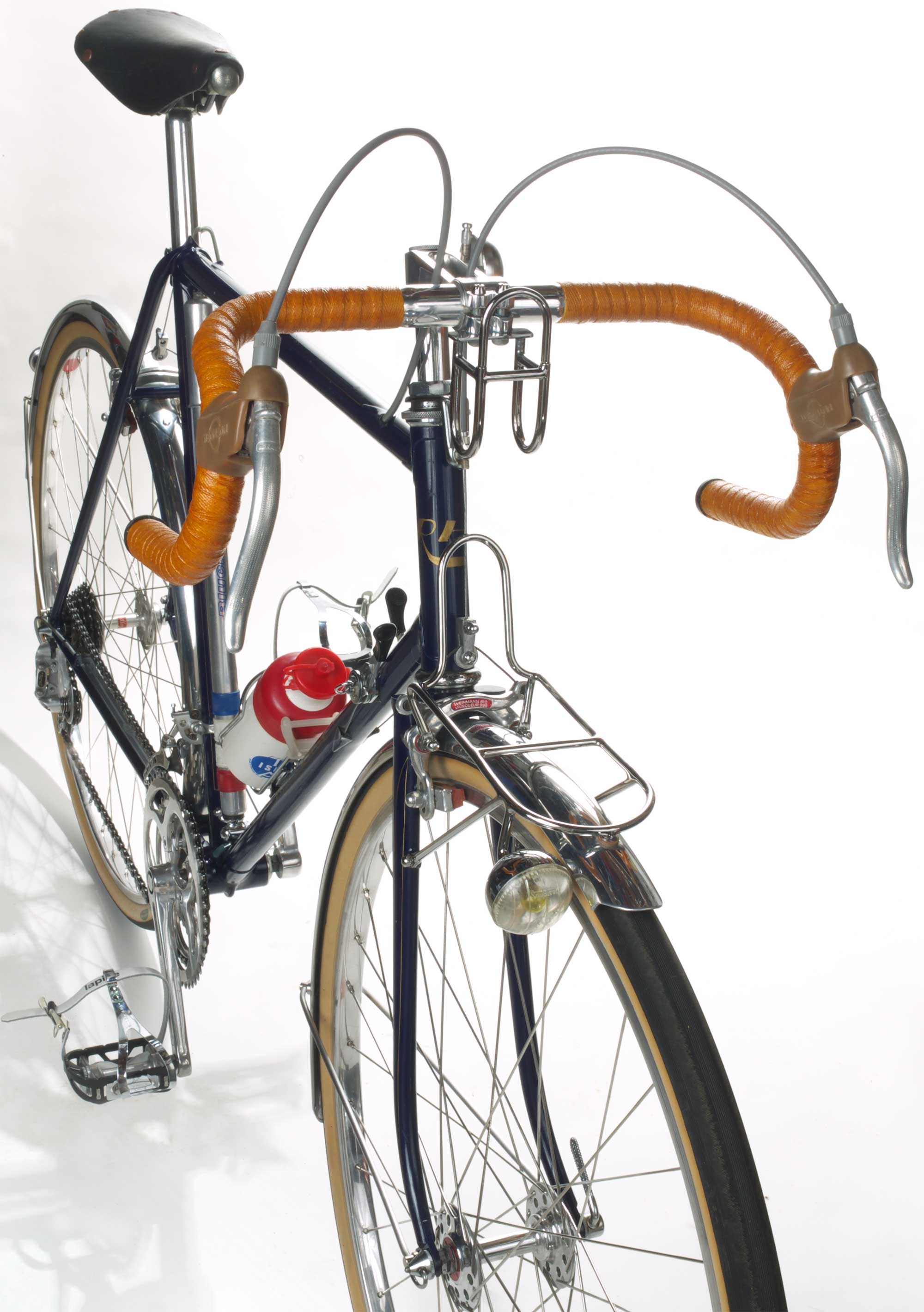
I made the Herse-style decaleur (handlebar bag holder) and had it brazed by Paul Sadoff who builds Rock Lobster framesets/bicycles. The front bag is a modern version of what would have been on the bike, made by Gilles Berthoud, I used a Crane bell to make a facsimile of the missing one, and the fenders are by Honjo, with a Kimura Billet reflector from Jitensha Studio, who also supplied the Champion rubber chainstay protector. The tires are by Grand Bois. The photos are by my friend and fellow bicycle aficionado, Anthony Alsberg. They are much larger than shown, so be sure to click to zoom them (and click again on the photo when the zoom opens in your browser because many browsers open a smaller version sized to fit first). Read the notes below the photos to learn more about this exquisite machine. Everyone who sees this bike asks, so I'll answer... yes, it rides magnificently. If you ever get a chance to pedal a René Herse, do not pass it up. Jim Langley
|
|
The leather saddle had been swapped for a modern anatomic vinyl model. The seatpost was original and quite tarnished. The headlight remained, however the generator and taillight were missing. The wiring was still inside the frame but cut at the ends. Modern vinyl handlebar tape had been installed on the original handlebars with the original Weinmann brake levers. The Herse stem was still there in nice shape. The integral bell was long gone.
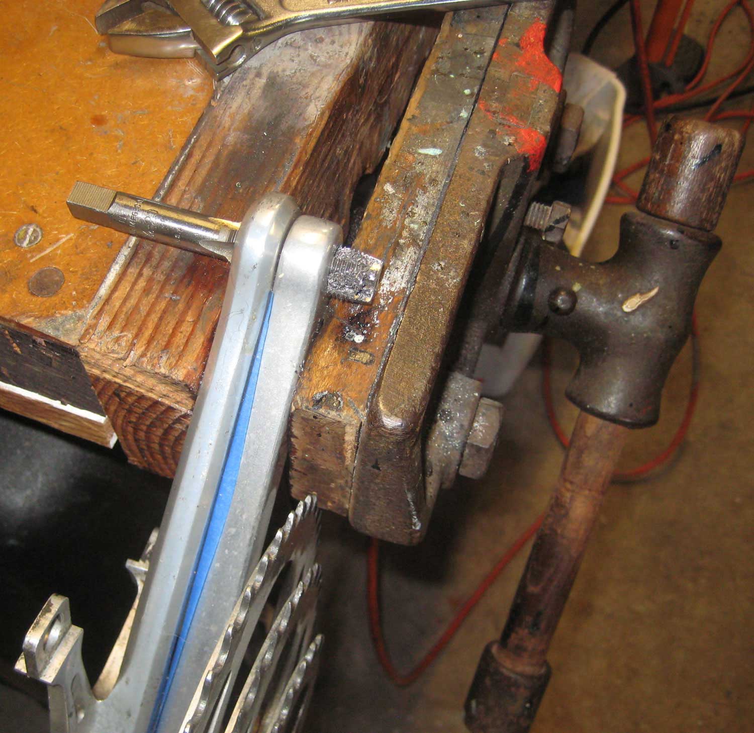
Dick brought the bike to me to fix this problem when it happened in the 1980s and I was able to remove the pedals, chase the threads and install them as close to correctly as possible. However, the pedals went in slightly crooked. Luckily Dick was able to ride without issues anyway. Repairing the crankarms was the first big challenge in bringing the bike back (photo). The list of new old stock parts includes (front to back): Stronglight headset (thanks Peter Weigle!), Weinmann brake levers (thank you Dale Brown at ClassicRendezvous!), Weinmann brake pads front and rear, Huret Jubliee shift levers (including the 3rd one for operating the generator), TA cage and bottle, Ideale saddle, Lyotard pedals with Christophe clips and Lapize straps, Bluemel pump with Campagnolo head, Huret Jubilee front derailleur, Ejac shift cables, Sedis chain and replacement rear Maxi-car axle. Inside the Berthoud handlebar bag are French maps of Paris and tools and spares from the 1970s. |
|
 Click to zoom |
|
|
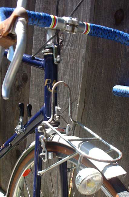
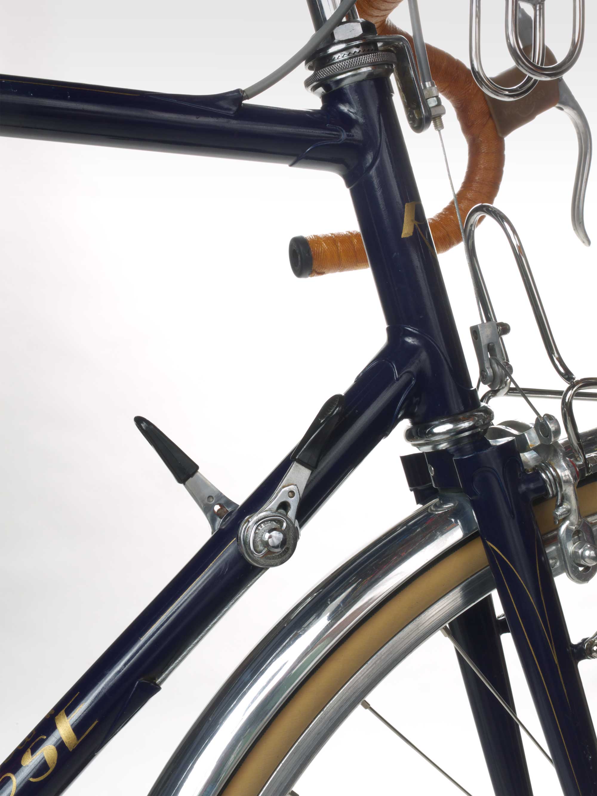
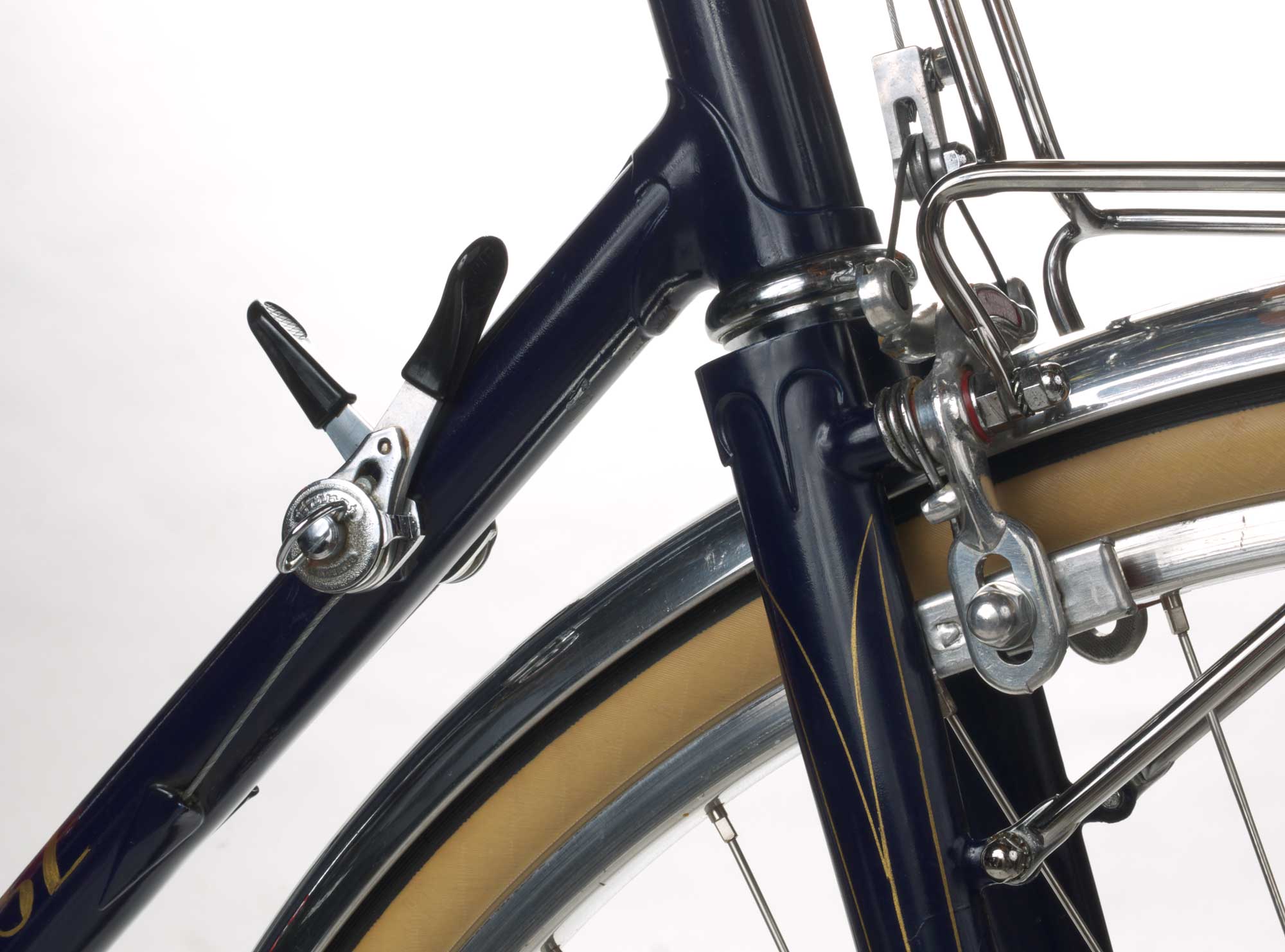 Click to zoom. Lovely head lugs and crown, pin striping and Herse rack and cable hanger |
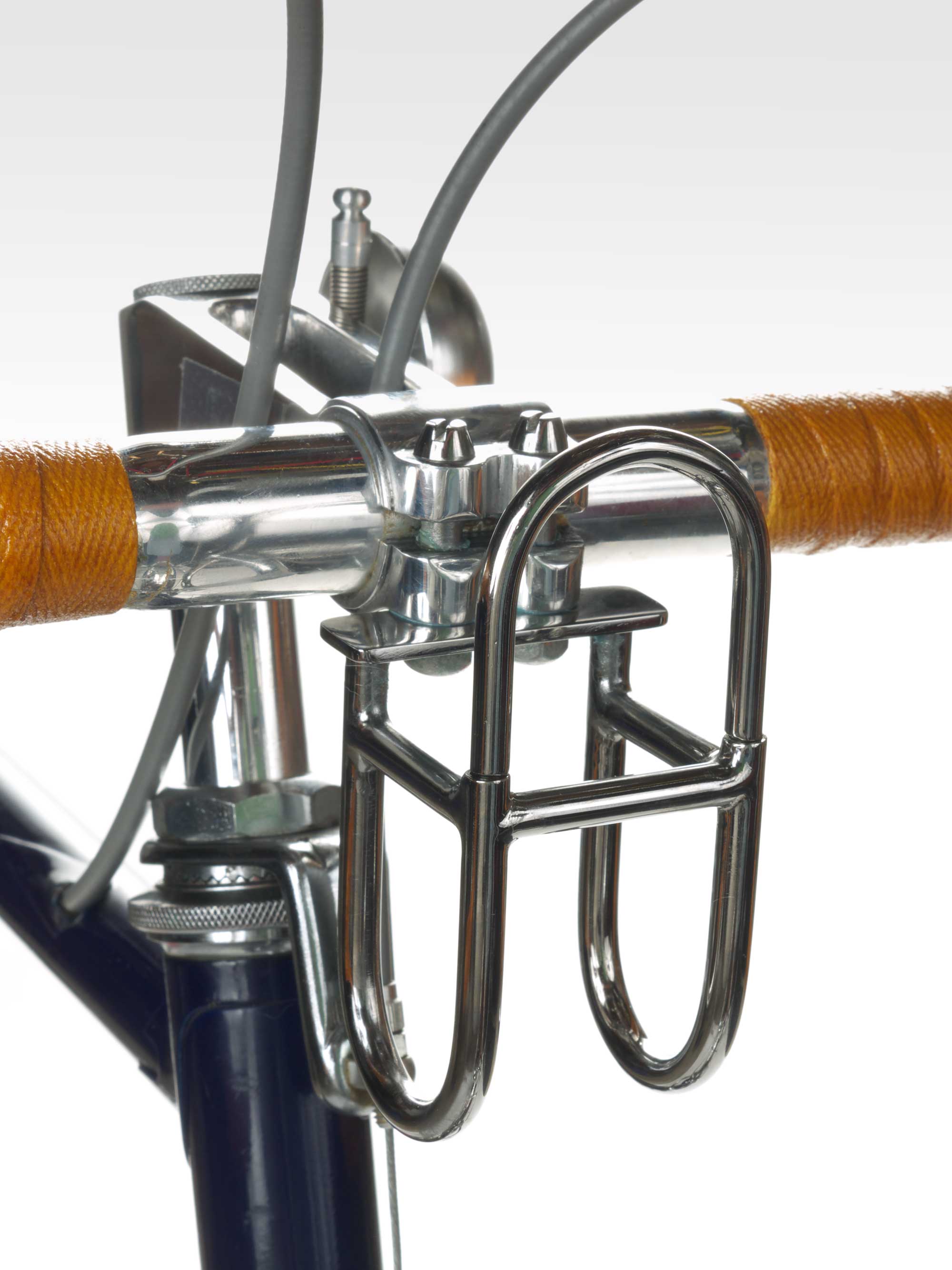 Click to zoom. Herse-style decaleur I made, Herse stem, 5 coats of shellac on original bars |
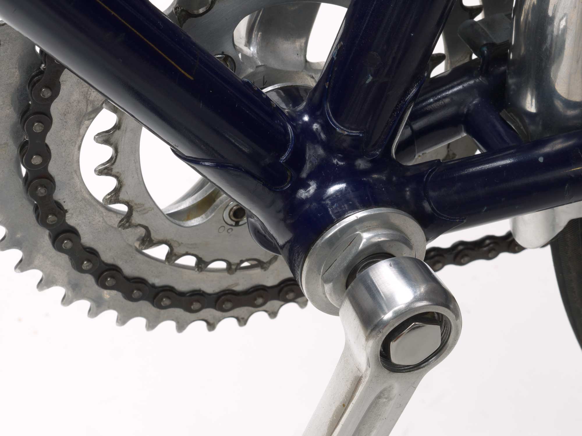
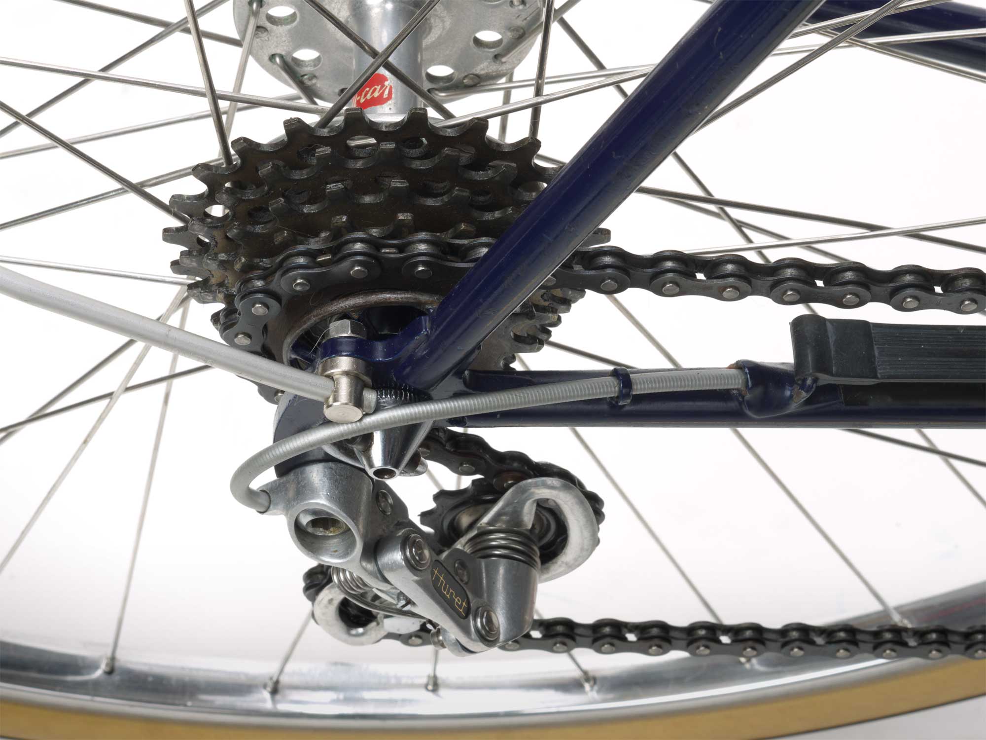 Click to zoom. Repos de chaine, rubber chainstay strap, internal shift cable routing, fine dropout-to-stays construction |
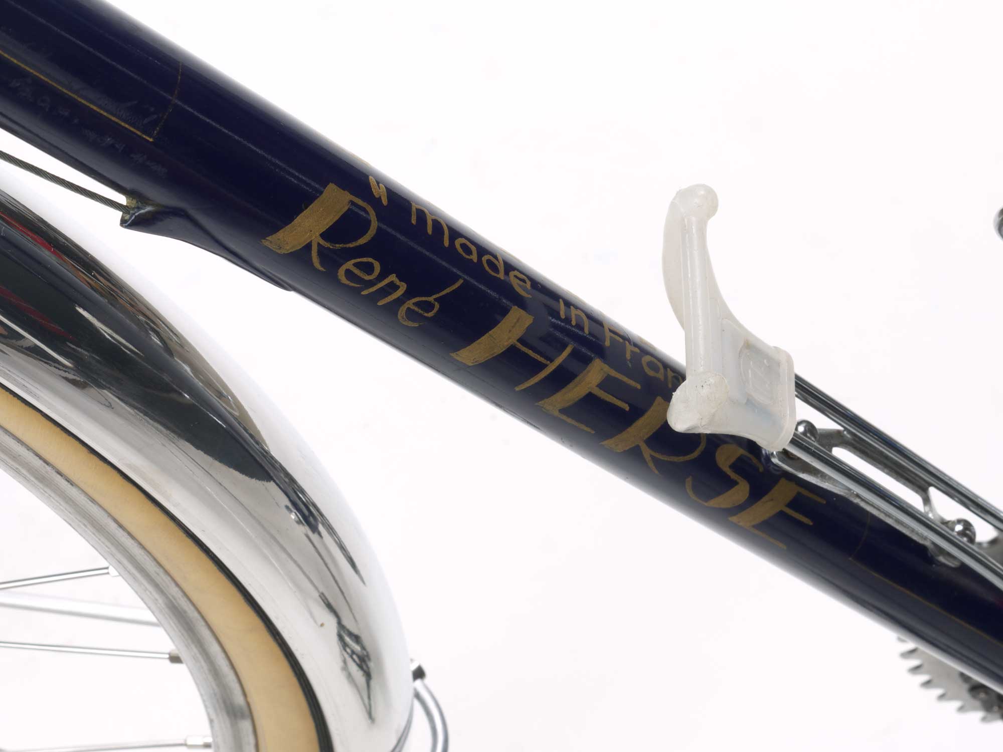 Click to zoom. Internal cable port and painted name, no decals here |
 Click to zoom. Internal cabling passes through tubes inside the frame, meaning threading new cables is as easy as pushing them through! |
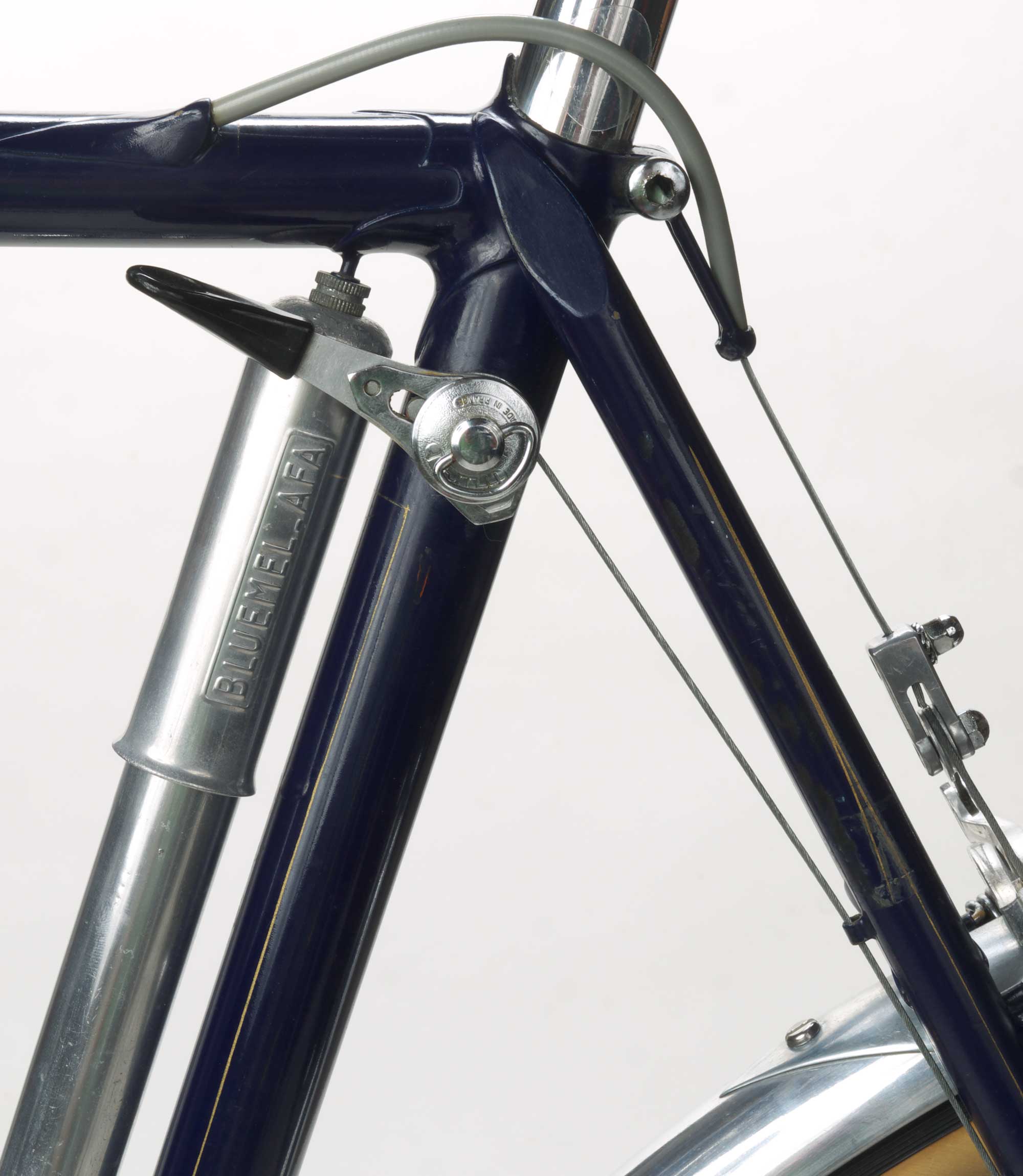 Click to zoom. Dynamo lever, sweet seat lug, internal cable port, pump peg on lug point, cable hanger integrated into seatpost binder, cable guide braze-on beneath seatstay and Herse-style fender triangle reinforcement I made |
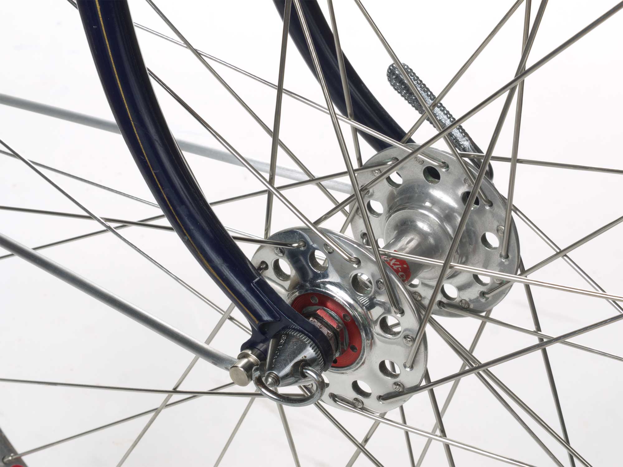 Click to zoom. Masterful dropout work and fork rake, lovely Maxi-car sealed-bearing hub |
 Click to zoom. |
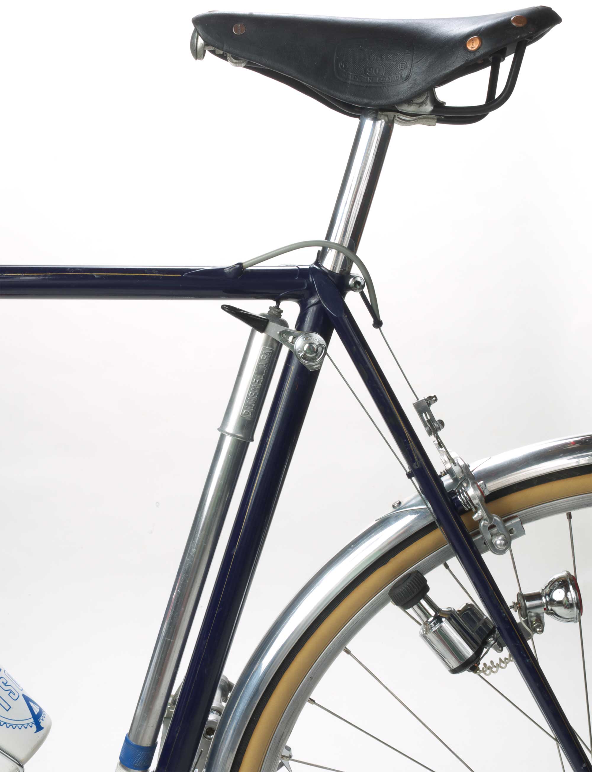 Click to zoom. Entire dynamo setup, Ideale saddle, Herse cable hanger |
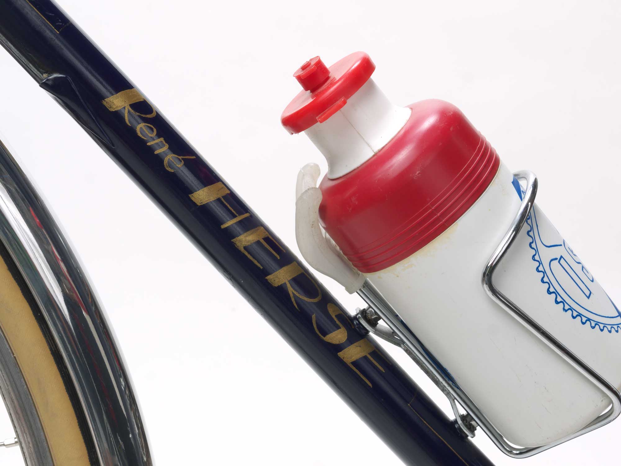 Click to zoom. TA cage and insulated TA bottle |
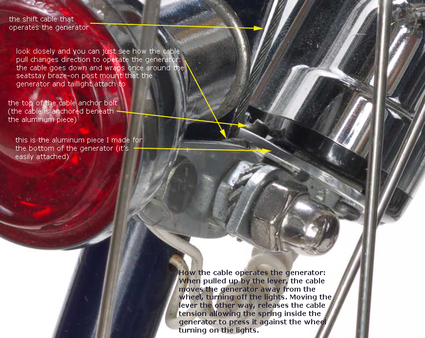
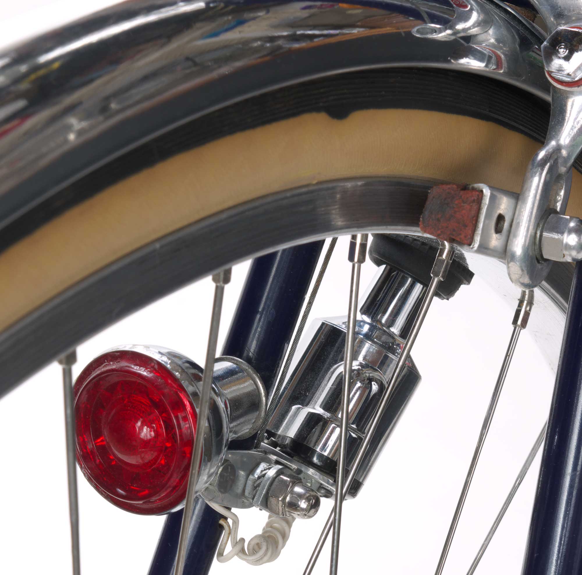 Click to zoom. Look closely to follow clever cable routing and see custom piece on Soubitez dymano required to let the lever turn it on/off |
 Click to zoom. Herse stem like new |
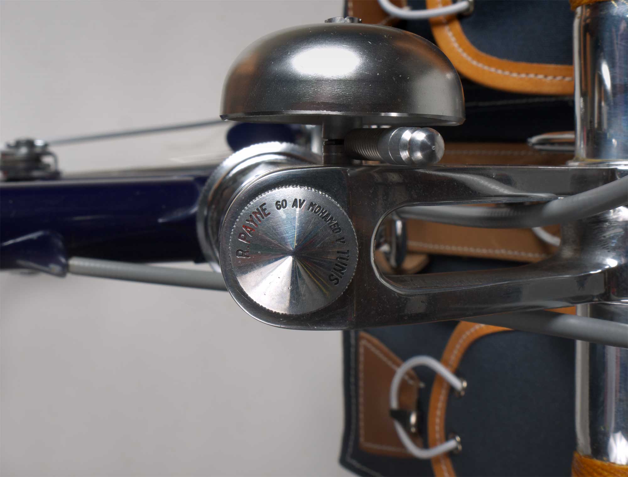 Click to zoom. Owner's name written in Herse knurled stem cap |
 Click to zoom. Loop on Herse rack mirrors decaleur's: 2-wheel artistry; headlight wire runs interally through hollow rack tubing, into fender and into fork steerer |
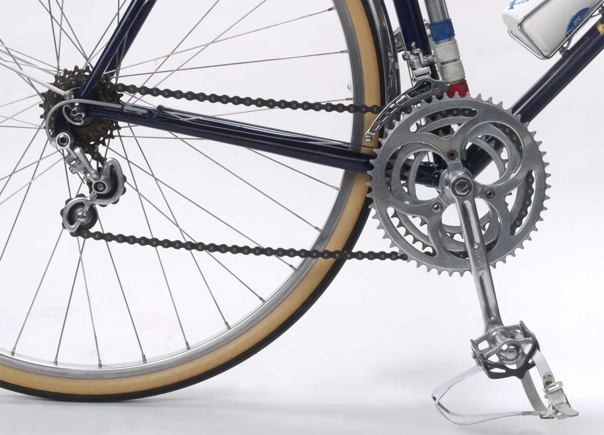 Click to zoom. Herse crankset |
René
Herse's ingenious generator lighting system explained The
generator and lever
Finally, through trial and error, I discovered the only possible way to route the cable to turn the generator on/off correctly. You can see all of this in this photo if you click to enlarge it. Look closely to see the cable anchor plate I made and the elegantly simple way the cable routes to change its direction of pull to move the generator in and out. The
wiring Getting
power to the headlight The second wire leaves the generator and goes into a hole in the seatstay. It only runs a short way before exiting the stay and entering the rear fender's rolled over edge. It travels inside the fender to the bottom of the fender, where it turns left and enters the chainstay. From there it goes forward into the bottom bracket shell and continues all the way up the down tube, ending at the head tube.
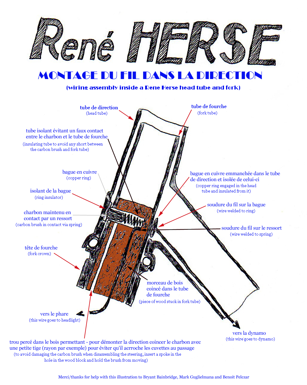
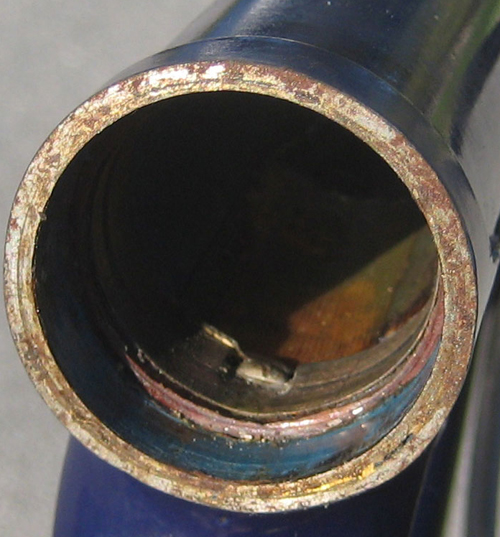
The second wire can't continue from the top of the down tube because the fork is in the way, and the fork has to be able to turn from side to side for steering. So, René Herse made a contact between where the wire stops at the head tube and the fork.
The small square hole you see in the copper ring and the cylindrically shaped piece in the hole is the end of the second wire, the one traveling from the generator all the way to this point at the top end of the down tube.
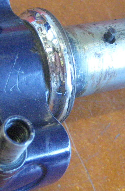
Both the copper ring and carbon brush assembly are insulated from the frame and fork (or else an electrical short would occur). In this photo of the carbon brush protruding from the fork steerer, you can just see a black shadow around part of the brush. It's some type of nylon or rubber that's insulating the brush assembly from the steerer. I can't see what insulates the copper ring from the head tube and/or exactly how the copper ring is held in place. The ring seems permanently attached, so perhaps it was bonded to the head tube with epoxy? All that's needed to get the electricity from the connection inside the fork, is the third wire that travels from the copper brush spring inside the fork, down into the front fender, then into the front rack's hollow tubing and all the way to the headlight! A fun detail is that the headlight is attached to its support arm on the rack with a chainring bolt. Maybe most amazing, once I attached the parts and connected what new electrical wire was needed to the old ones protruding from the frame, the 40 year old lights came to life; a testament to René Herse's brilliant design (pun intended). |
|